
A 25 mm welded-mesh label can mean two different things
A maintenance team is replacing a welded-wire panel on a conveyor guard. The old drawing says only “25 mm mesh, 3 mm wire.” One buyer reads that as a 25 mm opening. A fabricator reads it as 25 mm centre-to-centre pitch. Those are not the same panel: if 25 mm is pitch and the wire is 3 mm diameter, the nominal clear opening is 22 mm. That 3 mm difference can affect what can pass through the guard, the calculated open area, panel mass and whether the new panel fits the intended design.
For ordinary welded wire mesh, pitch is the centre-to-centre spacing of adjacent parallel wires. Clear opening is the free space between their inside edges. A supplier needs to know which one the number describes in each direction. This guide gives a repeatable way to state both, calculate the geometry and prepare an RFQ without treating a screen panel as a safety certification.
Use the site’s Open Area Calculator after the actual X/Y openings and wire diameters are known. Use the Wire Mesh Weight Calculator to estimate bare-mesh mass for a panel or order. Both tools expose their inputs and assumptions; neither validates a machine guard design or a finished frame.
Start with four dimensions, not one “mesh size”
Pitch X
Centre-to-centre spacing of wires running in one direction. This is not the free gap unless wire diameter is zero.
Pitch Y
Centre-to-centre spacing in the perpendicular direction. Rectangular welded mesh commonly has a different value here.
Wire diameter X/Y
State the nominal diameter belonging to each pitch. Equal diameters are common, but should not be silently assumed.
Clear opening X/Y
The usable gap between inside wire edges. This is the value needed for projected open-area calculations and physical-clearance discussions.
“25 × 50 mm welded mesh” remains ambiguous unless the drawing says whether the figures are clear openings or centre-to-centre pitches. The same issue appears when a sample is measured with a tape: measuring from wire centre to wire centre gives pitch; measuring from the inside of one wire to the inside of the next gives clear opening. Record the measurement basis on the drawing and in the purchase description.
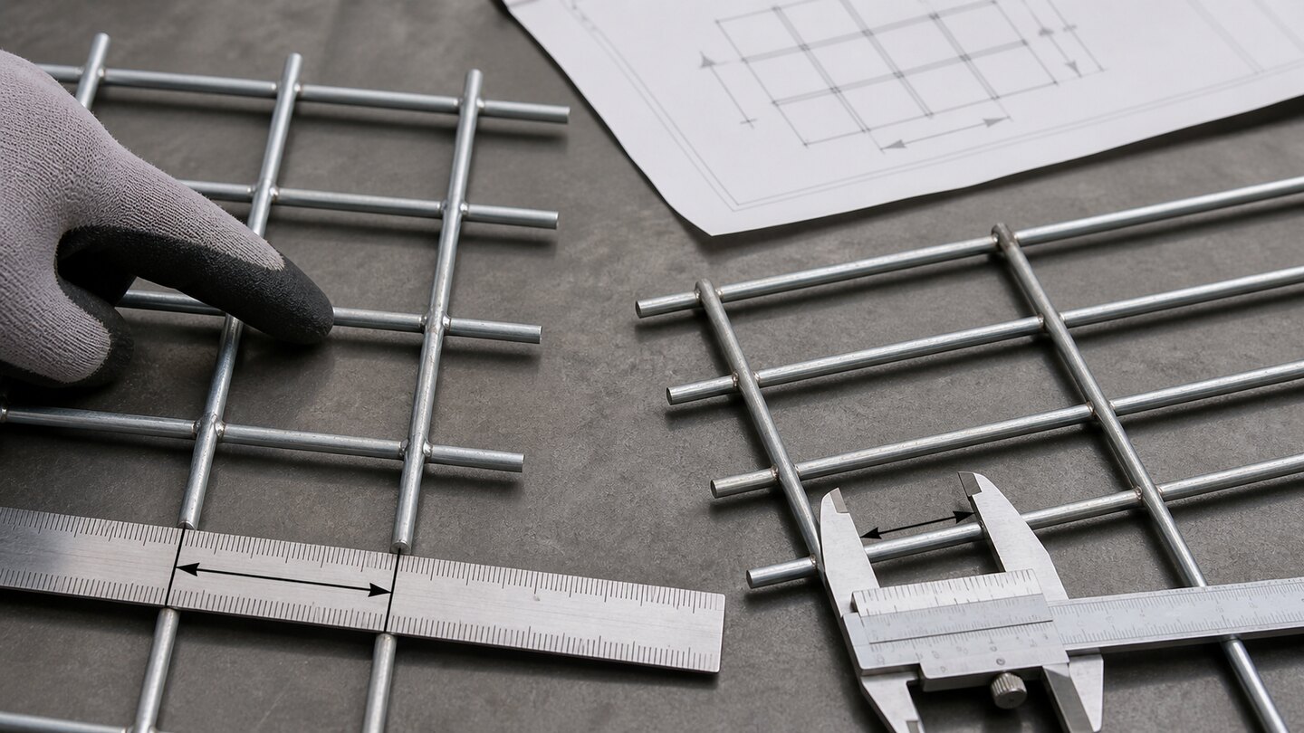
The geometry: pitch minus wire diameter equals nominal clear opening
For a flat welded grid with round wires, the starting geometry is simple. In each direction, subtract the diameter of the wire from the corresponding centre-to-centre pitch:
clear opening X = pitch X − wire diameter X
clear opening Y = pitch Y − wire diameter Y
projected open area (%) = opening X ÷ pitch X × opening Y ÷ pitch Y × 100
These are nominal projected values. They do not calculate weld shear strength, panel stiffness, coating build-up, frame clearance, hand access, pressure loss, airflow or a protective-distance requirement. Wires that are deformed, coated, bent after welding or used in a formed panel need their applicable drawing tolerances and finished-part checks.
Worked example: 25 mm pitch is not a 25 mm opening
Assume a regular welded grid with 25 mm pitch in both directions and 3 mm nominal round wire in both directions. The nominal clear opening is:
opening = 25 mm − 3 mm = 22 mm
projected open area = 22 ÷ 25 × 22 ÷ 25 × 100 = 77.44%
If a quotation instead uses a 25 mm clear opening with 3 mm wire, its pitch becomes 28 mm and the projected open area is 79.72%. It may look similar in a product photo, but it is a different geometry. Ask the supplier to repeat both pitch and clear opening on the quotation or approval drawing rather than relying on an unqualified “25 mm mesh” label.
Now consider a rectangular grid with 25 mm pitch X, 50 mm pitch Y and 3 mm wire in both directions. The calculated openings are 22 × 47 mm, and the projected open area is 82.72%:
opening X = 25 − 3 = 22 mm; opening Y = 50 − 3 = 47 mm
open area = 22 ÷ 25 × 47 ÷ 50 × 100 = 82.72%
Enter those four values directly in the Open Area Calculator. The result is useful for comparing stated geometry across like-for-like panels. It is not a measured airflow percentage or a promise of guard performance.
Do not mix a welded grid with woven-mesh terminology
Woven square-opening cloth is normally described by mesh count (openings per linear inch), wire diameter and aperture. Welded mesh is ordinarily better described by X/Y pitch or clear opening, X/Y wire diameter, sheet or roll size, material and finish. Applying “mesh count” arithmetic to a welded 25 × 50 mm grid produces a misleading result because the construction is different.
Similarly, a supplier’s “wire gauge” label is not a finished specification. Gauge designations vary by system and do not state the actual wire diameter, coating effect or tolerance. For any order that must fit a drawing, state the nominal diameter in mm or inch and name the applicable tolerance or inspection method. The gauge-versus-diameter guide explains why a gauge-only RFQ is risky.
Use open area for a comparison, not a safety or flow claim
Projected geometric open area is the proportion of a flat projected grid occupied by gaps. It is helpful when a buyer is comparing two regular grids, but it leaves out several real-world factors: wire crimp or deformation, welded intersections, panel frame, angle to flow, blockage, dust loading, fan curve, pressure difference and installation details. For air or liquid service, obtain application-specific performance information or test the intended assembly.
For machine guarding, opening geometry is only one part of the decision. OSHA’s general machine-guarding requirement describes protection from hazards such as point-of-operation, nip-point and rotating-part exposure; it also requires a guard not to create an accident hazard itself. 29 CFR 1910.212 is a U.S. requirement, not a global sizing table for every mesh panel. The regulation’s separate fan-blade rule includes a one-half-inch opening limit in the particular conditions it describes; do not copy that figure into another machine, country or hazard assessment without competent review.
State the actual equipment, hazard, operating mode, location, applicable jurisdiction and required standard or risk assessment in the project file. A calculated opening cannot certify that a guard prevents access, contains ejected material, withstands impact or meets a local rule.
Mass example: separate bare mesh from the finished guard
The Wire Mesh Weight Calculator treats welded mesh as two orthogonal sets of straight round wire. With the 25 × 50 mm pitch, 3 mm wire and steel density used by the tool (7,850 kg/m³), the nominal bare-mesh estimate is about 3.33 kg/m². A 1.2 × 2.0 m panel therefore has a bare-mesh estimate of about 7.99 kg before a frame, fixings, kick plate, bends, overlaps, coating, cut-outs or handles are considered.
bare mesh only: 3.33 kg/m² × (1.2 m × 2.0 m) = 7.99 kg
finished guard mass = bare mesh + separately specified frame, hardware and fabrication
This separation prevents a common purchasing mistake: a supplier’s mesh kg/m² figure is not automatically the shipping mass or lifting mass of a framed guard. Add the frame profile, fasteners, coating system, packaging and completed-panel drawing to a transport or handling calculation.
What to inspect on a replacement sample
- Identify the construction. Confirm that it is welded wire, not woven cloth, expanded metal, perforated sheet or another screening product.
- Measure X and Y separately. Record clear opening, pitch and wire diameter in each direction. Do not assume a rectangular panel is square.
- Measure more than one location. Compare centre, edges and a practical sample of the delivered panel or roll against the agreed inspection plan.
- Check the finished condition. Note coating, galvanizing, cut ends, burrs, weld appearance, flatness, frame attachment, bends and any local distortion.
- Keep the evidence together. Retain labelled photos, the supplier drawing revision, tool result, measurement method, instrument identification where required, material documents and disposition.
A caliper reading on one opening is evidence of that observed point, not proof that every opening, weld or safety function conforms. Align sampling, tolerance, acceptance authority and remedy before delivery. The receiving-inspection checklist can help organize that record.
RFQ wording that makes the geometry auditable
Use a drawing wherever possible. The following wording makes clear that the supplier must state how dimensions are interpreted:
Welded wire mesh panel for [equipment/location]; material and finish: [state];
nominal pitch: [X] mm × [Y] mm centre-to-centre; nominal wire: [X] mm × [Y] mm;
or nominal clear opening: [X] mm × [Y] mm, with resulting pitch stated by supplier;
panel size, frame, bends, edge treatment, fixings and drawing revision: [state];
supplier to state dimensional tolerances, measurement basis, coating condition and inspection record offered;
project safety / access / local compliance requirement: [state separately]; purchaser and supplier to agree acceptance plan.
Do not write both “25 mm opening” and “25 mm pitch” for 3 mm wire unless the contradiction is intentional and explained. If only an old panel is available, photograph the context, measure both directions and submit the data through Request a Recommendation before converting a maintenance note into a new purchase order.
A practical selection path
- Define the use. Separate visual enclosure, ventilation screen, animal containment, product separation and machine-guarding needs. Do not merge their acceptance criteria.
- Choose the dimension basis. Specify clear opening when the free gap matters; specify pitch when fabrication layout matters; ideally show both on the approval drawing.
- Calculate nominal geometry. Use the Open Area Calculator for the stated X/Y opening and wire values, and label its result as geometric.
- Estimate the right mass scope. Use the weight tool for bare welded mesh, then add fabricated components separately.
- Validate the finished panel. Check the actual construction, dimensions, coating, edges and equipment-specific requirement against the agreed drawing and inspection plan.
Frequently asked questions
Is a 25 mm welded mesh opening measured between wires?
It can be, but the phrase alone is ambiguous. Ask whether 25 mm is the clear opening or the centre-to-centre pitch, and state the nominal wire diameter. With 3 mm wire, 25 mm pitch gives a nominal 22 mm clear opening.
Can I calculate open area from pitch only?
No. You need the wire diameter in each direction as well. For ordinary round-wire geometry, clear opening is pitch minus wire diameter; then the X and Y opening fractions are multiplied.
Does 82.72% projected open area mean 82.72% airflow?
No. It is a geometric projected ratio for the stated flat grid. Actual airflow depends on the fan, pressure, panel frame, installation, angle, blockage and service condition.
Can this article certify a welded panel as a machine guard?
No. Guarding needs equipment-specific hazard assessment, applicable rules and validation of the complete installed guard. The calculations here help describe mesh geometry; they do not establish safety compliance.
Should I order by gauge or by diameter?
Order by nominal diameter and its stated tolerance or inspection basis. A gauge label can be supplementary, but it is not a substitute for a dimensioned specification.