A “2 × 10 mm long-slot screen” can still be an incomplete RFQ
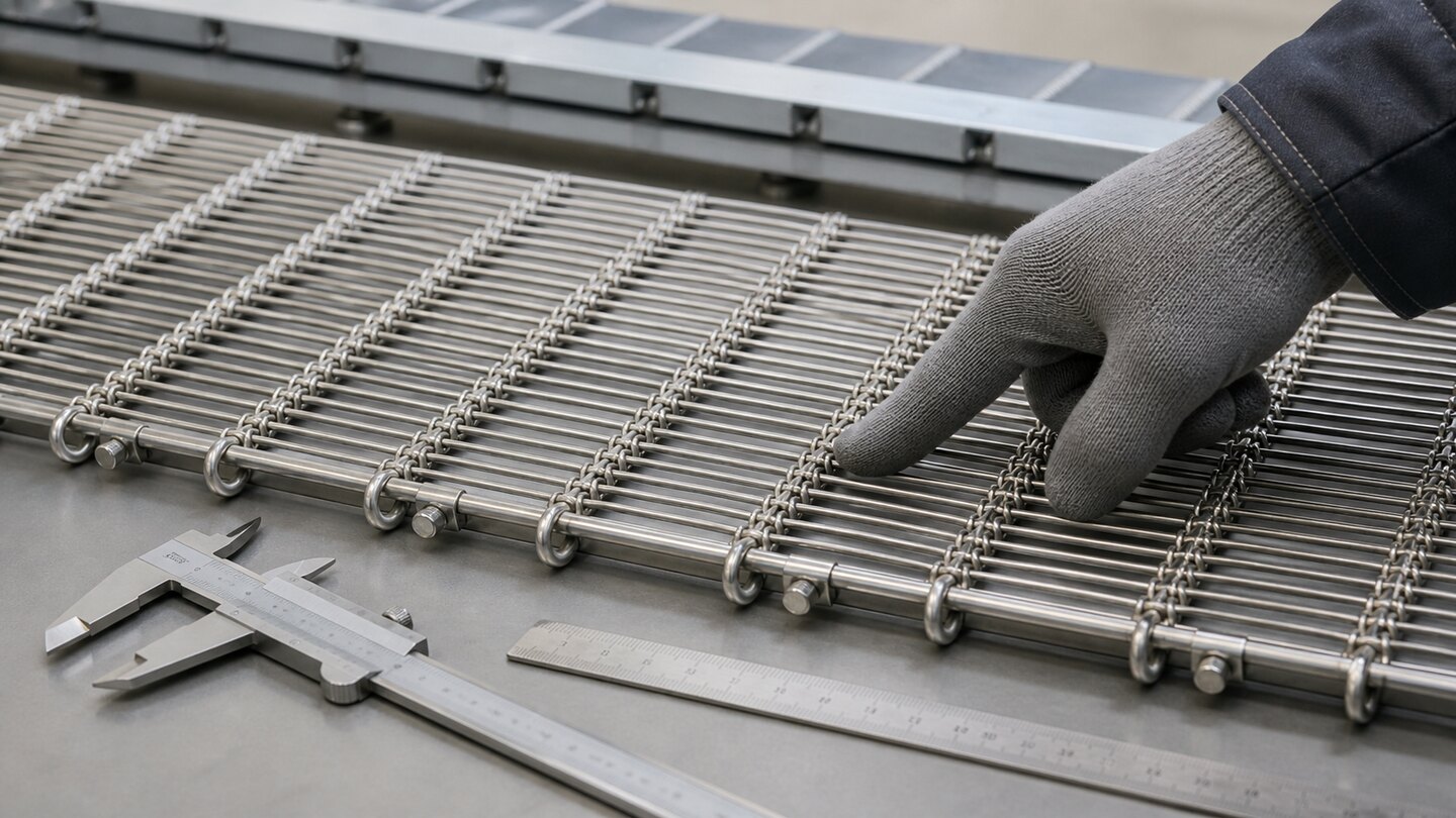
A maintenance buyer has a retained screen panel in hand. The caliper shows a narrow opening of about 2 mm and a long opening of about 10 mm. The note sent for quotation says “2 × 10 mm long-slot mesh.” That looks specific, but it can still leave a supplier, drafter and installer looking at different finished panels.
The missing fact is direction. Does the 10 mm slot run along the panel length, across the panel width, or along material travel? Which way are the support rails, hooks or tensioning edges? Are the wire diameters the same in both directions? Is the quoted percentage the open area of the screening field, rather than the complete framed panel? A useful RFQ fixes those questions before price is compared.
This guide gives a practical way to name X/Y directions, record the geometry, calculate the stated projected open area when the construction is suitable for that model, and ask for a screen assembly without silently assuming performance. It is intended for industrial screening and selection work; it is not a guarantee of separation efficiency, throughput, service life or product behaviour.
First, name the direction from a drawing datum
“Long slots horizontal” is not reliable purchasing language. A panel can be photographed on a bench, turned 90 degrees in an email, or installed in a different orientation from the one assumed by the quotation. Instead, select a durable reference on the drawing and state it in words:
Panel X direction
Define X as the panel width, or as the direction between two named side edges. State the clear opening and nominal wire diameter in that direction.
Panel Y direction
Define Y as the panel length, material-travel direction, or another labelled datum. State whether the long axis of the slot lies in X or Y.
Installation reference
Show material travel, support rails, hook edges, tensioning edges and the face of the panel. A screen may be geometrically correct yet installed in the unintended orientation.
Inspection basis
Say whether dimensions are nominal drawing values, measured observations from a worn sample, or acceptance measurements on the new panel.
For example: “Clear opening 2.00 mm in X and 10.00 mm in Y; long slot axis parallel to material travel shown on drawing; nominal wire diameter 1.00 mm in X and 1.50 mm in Y.” The labels can be reversed if the drawing says so. The important point is that the dimensions and the view are tied together.
Separate opening geometry from operating performance
A rectangular clear opening can be described by its two clear dimensions. The wire construction also has two directions. In a simple orthogonal representation, the X pitch is the X clear opening plus the projected X wire diameter, and the Y pitch is the Y clear opening plus the projected Y wire diameter. The projected open area is the open fraction in X multiplied by the open fraction in Y:
pitch X = clear opening X + wire diameter X
pitch Y = clear opening Y + wire diameter Y
projected open area (%) = (opening X ÷ pitch X) × (opening Y ÷ pitch Y) × 100
This is the same transparent model used by the Open Area Calculator. Use it only when the stated construction can honestly be represented by independent orthogonal clear openings and projected wire diameters. It does not model every crimp profile, self-cleaning screen geometry, non-uniform weave, border, hook, support rail, frame or formed panel. It also does not predict capacity, blinding, wear, particle orientation, airflow, pressure drop or separation result.
Worked example: 2 × 10 mm slot, two wire diameters
Assume a specification states a 2.00 mm clear opening in X, a 10.00 mm clear opening in Y, a 1.00 mm nominal wire diameter in X and a 1.50 mm nominal wire diameter in Y. The calculation is:
pitch X = 2.00 + 1.00 = 3.00 mm
pitch Y = 10.00 + 1.50 = 11.50 mm
projected open area = (2.00 ÷ 3.00) × (10.00 ÷ 11.50) × 100
= 57.97%
Enter those four values in the Open Area Calculator to reproduce the 57.97% result. Keep the input record with the drawing: the result is meaningful only for these stated values and the model’s stated scope. It is not a supplier tolerance, a guaranteed effective open area, or a claim about what a particular feed will do on a machine.
Turning this idealised panel through 90 degrees does not change the calculated 57.97%: the same repeating geometric cell still contains the same open rectangle and projected wire area. What changes is the long slot’s relationship to the product path, supports, panel shape, hooks and installation drawing. That is why open area alone cannot stand in for orientation.
Why the long axis deserves its own RFQ field
In a screening assembly, the long opening can be parallel or perpendicular to material travel. It may run with or across a support pattern. Its direction may determine whether the replacement fits the hooks or how an inspector reads the panel against the drawing. Those are interface and design questions, not a universal rule that one orientation is “better.” The correct direction has to come from the equipment requirement, approved drawing and responsible engineering review.
Write the direction explicitly, then add the facts needed to preserve it through purchasing:
- Panel orientation: show a top view with X, Y, material travel and a labelled long-slot axis.
- Screening field: state clear opening X × Y, nominal wire diameter X × Y, weave or crimp description, material and any stated tolerance.
- Assembly: state finished length and width, hook type, edge treatment, frame, rails, backing, cut-outs, mounting points and flatness or tensioning details.
- Reference face: identify the working face and the direction from which dimensions are read where that affects the supplied assembly.
- Acceptance: say what will be checked at approval or receipt: drawing, photographs, opening measurements, material documents, sample or representative trial.
These fields prevent a common failure mode: an otherwise plausible quote describes the mesh field, but not the orientation or interface of the finished replacement panel.
Construction type still matters
“Long slot” describes opening shape, not a complete construction. Regular woven wire cloth, pre-crimped screens, self-cleaning or non-uniform screen designs, slotted plate and other screening media can use different manufacturing language and different ways of describing an opening. Do not treat their geometry as interchangeable merely because a narrow and a long dimension are visible.
For pre-crimped or pressure-welded wire screens, ISO 4783-3:1981 identifies aperture width, wire diameter, wire material and type as designation elements within its stated scope. That reinforces a practical RFQ discipline: the opening alone is not the whole designation. The standard does not replace the finished-panel drawing, its installation orientation or a duty-specific validation plan.
When the panel is regular square woven cloth rather than long-slot geometry, the Woven Wire Mesh Calculator can help check nominal aperture, pitch and projected open area from mesh count and wire diameter. Do not force an asymmetric long-slot construction into that square-mesh model. Select the tool that matches the proposed geometry, and retain the supplier’s actual construction data where the geometry is not an orthogonal grid.
Measure a retained panel without turning wear into a nominal size

Old panels are valuable evidence, particularly when the original drawing is unavailable. They can also be worn, stretched, corroded, patched, cut down or installed after a prior modification. Record observations separately from the new specification.
- Photograph before removal. Capture both faces, product-travel direction, supports, hook edges, frame, identifiers and nearby interfaces. Add a scale only if it does not obscure the feature.
- Mark a physical datum. Identify “this edge is upstream,” “this edge is panel width,” or another unambiguous reference before the sample is rotated on the bench.
- Measure more than one position. Take X and Y clear-opening readings at representative locations, noting localized wear, damaged wires or distorted areas.
- Record wire and assembly dimensions. Measure or estimate wire diameter in both directions where feasible, then record panel size, hook profile, rail spacing, backing and fastener details.
- Preserve uncertainty. Label values as observed measurements if original nominal dimensions are unknown. Ask the supplier to state assumptions rather than converting one caliper reading into a false tolerance.
Use the wire-mesh sample measurement guide to organise photos and basic dimensions. If the replacement is for a vibrating screen, also collect the panel and hook information in the vibrating-screen replacement RFQ guide. The objective is a reviewable evidence package, not a claim that one field measurement proves original design intent.
Where the open-area figure belongs in a comparison
Projected open area is useful for comparing stated geometric fields after the construction, opening dimensions and wire diameters are aligned. It is especially useful when two proposals look similar but their X/Y wire diameters or pitches differ. In the example above, a change from 1.50 mm to 1.80 mm in the Y wire would change the stated geometric result, even though the visual label “2 × 10 mm” had not changed.
But a complete panel includes more than its repeating opening. Borders, hooks, frames, rails, backing cloth and non-screening margins reduce the active field or change the installed assembly. Product condition, moisture, particle shape, loading, amplitude, pressure, fouling, support and operation affect actual results. Do not turn a calculated percentage into a guarantee for throughput, flow or screening efficiency. For an important process decision, agree a representative validation method with the equipment owner and responsible supplier.
RFQ wording that makes direction auditable
Attach a dimensioned drawing whenever possible. The following wording is a starting format, not a replacement for engineering of the equipment or finished screen:
Application and installation reference: [state process and attach drawing];
panel datum: X = [named width/edge], Y = [named length/material travel];
clear opening: X = [ ] mm, Y = [ ] mm; long slot axis = [parallel to X / parallel to Y];
nominal wire diameter: X = [ ] mm, Y = [ ] mm; construction/weave/crimp = [ ];
material, finish and any traceability/document requirement: [ ];
finished panel: overall size, hooks/edges, frame, supports, backing, cut-outs and mounting: [ ];
supplier to state tolerance, geometry basis for any quoted open area, assumptions and inspection method;
acceptance: [drawing approval / sample / receipt inspection / representative validation].
If you have only a sample and photographs, send those facts through Request a Recommendation. State what is unknown. A clear unknown is safer than a complete-looking RFQ that omits slot direction or the finished-panel interface.
Quick checks before releasing the purchase order
Geometry
Are X/Y clear openings and X/Y wire diameters stated in millimetres, with the construction type identified?
Orientation
Does the drawing show the long slot axis relative to material travel, panel edges, rails and hooks?
Calculation scope
If an open-area percentage is quoted, does its calculation match the actual screen geometry and exclude unsupported performance claims?
Assembly
Are the finished panel size, borders, frame, supports, cut-outs and mounting details shown rather than assumed?
Frequently asked questions
Does rotating a long-slot panel change the calculated open area?
For the same ideal orthogonal opening and wire geometry, no: rotation does not change the geometric area fraction. It can change the slot’s relationship to product travel, supports, hooks and the installation drawing, so the direction must still be stated.
Can the Open Area Calculator predict screening efficiency?
No. It reports a projected geometric open-area result for the entered orthogonal values. It does not predict capacity, particle behaviour, blinding, wear, airflow, pressure drop or the performance of a finished screen assembly.
Are a 2 × 10 mm slot and a 10 × 2 mm slot the same specification?
They describe the same two dimensions only if the drawing also makes the X/Y direction clear. In an RFQ, write both dimensions against named axes and state the long-slot orientation.
Do I need both wire diameters?
Yes when they differ or when the construction requires directional description. The two wire diameters affect the stated pitches and projected geometry. Record the actual proposed construction rather than assuming one value applies in both directions.
Can a used panel supply all the values?
It can provide useful evidence, but wear, deformation and prior modification may hide original nominal values. Preserve photographs and observed measurements, then resolve missing information through drawings, records and supplier review.