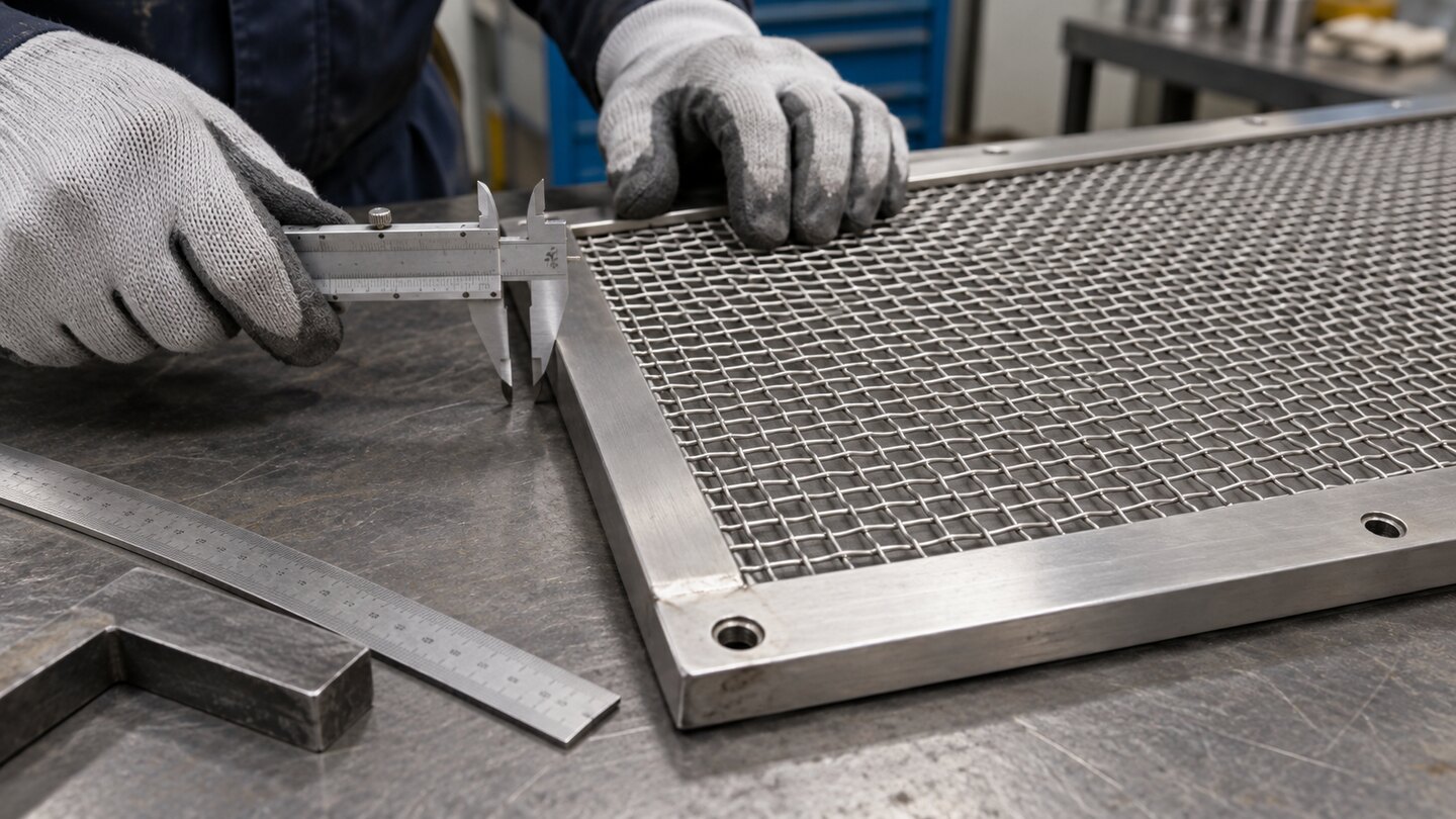
A cut-to-size mesh panel is more than length × width
A buyer needs a replacement panel for an enclosure, basket, process cover or fabricated frame. The request says “stainless wire mesh, 1,200 × 600 mm.” The supplier can still make several materially different parts: an unframed sheet cut to those overall dimensions; a mesh field inside a 40 mm border; a panel welded into a frame; a panel with mounting holes; or a panel with an edge condition that is unsuitable for the way it will be handled or installed.
Length and width are essential, but they do not identify the active mesh field, datum edges, cut-outs, corner treatment, attachment method, flatness expectation or inspection basis. This guide turns a short size note into a usable drawing and RFQ. It also shows where the site’s Wire Mesh Weight Calculator can provide a transparent bare-mesh planning estimate—and where it stops.
The goal is to describe the component that must be supplied. It is not to certify stiffness, safety, containment, fit, throughput or service life. Those depend on the complete construction, application, supports, loading, fabrication and agreed validation.
Start with three separate areas on the drawing
A useful panel drawing distinguishes the areas that are often folded into one overall size:
Overall envelope
The maximum finished length and width, measured from named outside edges. This is normally the fit or packaging dimension.
Active mesh field
The area intended to screen, ventilate, retain or visibly cover the opening. It can be smaller than the panel because of borders, frames or mounting zones.
Exclusion zones
Margins, overlaps, frame lands, holes, bends, cut-outs and attachment areas. Show their location from named datums; do not leave them implied by a product photo.
Finished edges
Describe the intended edge treatment: trimmed, enclosed, hemmed, framed, welded or another stated detail. Do not assume a raw cut is interchangeable with a finished edge.
For a flat panel, use a front view with one corner called datum A and two perpendicular base edges called X and Y. Dimension every hole, cut-out and active-field boundary from those datums. “Hole 20 mm from each side” is less auditable than “hole centre X = 20.00 mm from datum A edge; Y = 20.00 mm from datum B edge,” especially after the drawing is rotated or quoted in another unit system.
Specify the mesh field before you specify the perimeter
The panel size does not tell a fabricator the mesh construction. State whether it is square woven cloth, rectangular welded mesh or another construction; then state the geometry, material and finish at the level the application requires. For regular square woven cloth, a complete starting description includes mesh count or clear aperture, nominal wire diameter, weave, material and units. For welded rectangular mesh, state X/Y pitch or clear openings and X/Y wire diameters. Avoid converting a woven construction into welded-grid terminology, or vice versa.
Use the Woven Wire Mesh Calculator when the intended product is regular square-opening woven cloth and mesh count plus nominal wire diameter are known. Use the Open Area Calculator only for an orthogonal clear-opening and wire model. Neither tool designs an edge, predicts a finished panel’s strength, validates a guard or produces a fabrication tolerance.
Worked drawing example: 1,200 × 600 mm is not the active area
Assume a flat stainless woven mesh panel has an overall finished envelope of 1,200 mm × 600 mm. The drawing also calls for a 1,120 mm × 520 mm active mesh field, centered within the envelope. The arithmetic shows why both pairs of dimensions need to appear:
overall area = 1.200 m × 0.600 m = 0.7200 m²
active field = 1.120 m × 0.520 m = 0.5824 m²
border in X = (1,200 − 1,120) ÷ 2 = 40 mm each side
border in Y = (600 − 520) ÷ 2 = 40 mm each side
The active field is 0.5824 m², not the full 0.7200 m². If the edge is a frame land or non-screening margin, an open-area percentage calculated for the repeating mesh cell should not be presented as the open area of the completed panel. Keep the screening-field geometry and the completed-panel drawing as separate records.
Now assume the mesh field is 10 openings per inch, 1.20 mm nominal wire, stainless steel 304. The Weight Calculator uses a 7,930 kg/m³ reference density and a straight-wire woven model. For the full 1.200 × 0.600 m piece, it gives an estimated bare-mesh mass of about 5.08 kg:
nominal mass per area ≈ 7.062 kg/m²
area per piece = 1.200 × 0.600 = 0.720 m²
estimated bare-mesh mass ≈ 7.062 × 0.720 = 5.08 kg
12 identical bare pieces ≈ 61.01 kg
Enter the construction, material, finished width, finished length and quantity in the Wire Mesh Weight Calculator to reproduce the model. It excludes or approximates crimp, coating, selvage, frames, hooks, cut-outs, overlaps and fabrication. A framed panel, added fasteners or a cut-out therefore needs a separate bill of materials or actual weighing method. The calculation is a procurement and handling comparison value—not a certified delivered weight or lifting instruction.
Edge language should describe the required interface
“Cut to size” tells a supplier that a stock roll or sheet must be divided. It does not state what the edge is expected to do. A raw cut can leave exposed wire ends; a trimmed or enclosed edge can change the finished size, active field, mass and attachment method; a frame can provide stiffness and mounting features but becomes a separate fabricated component. Describe the edge by its intended drawing detail rather than assuming one term covers every option.
- State the finished boundary. Identify which line is the controlled overall edge. If an edge is folded, framed or enclosed, do not use the pre-fabrication mesh blank size as the finished-panel dimension.
- State the edge treatment. Use a drawing note or section view for the intended condition. Include any permitted projecting ends, enclosed wire requirement or corner treatment only when the order actually requires it.
- State the attachment. Identify weld locations, clamp zones, adhesive area, bolts, holes, frame profile or other interface. “Suitable for mounting” is not a measurable requirement.
- Separate appearance from acceptance. If burr condition, weld appearance, cleanliness or surface finish matters, define the method, sample, comparator or acceptance record. Do not make an unmeasurable word such as “perfect” the sole criterion.
For a replacement part, photograph the installed face and both sides before removal. The wire-mesh sample measurement guide helps preserve evidence. A worn old edge may explain a failure, but it is not automatically the specification for the new part.
Flatness, squareness and diagonals: ask for a measurable check
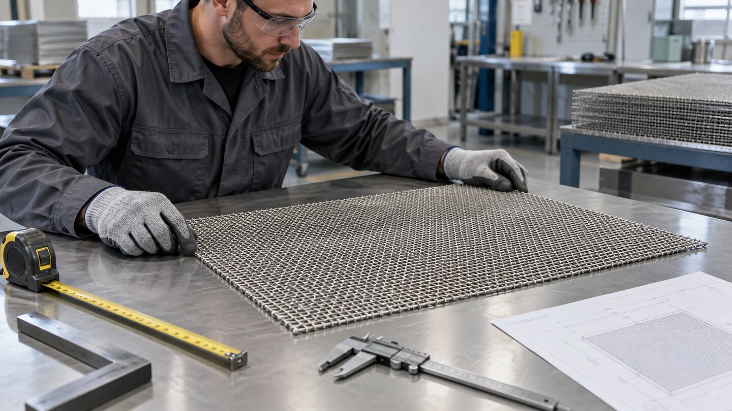
A rectangular panel can have the correct length and width yet be out of square, bowed or twisted. Whether that matters depends on the sealing surface, clips, frame, clearance and application. If it matters, put the condition and measurement basis on the drawing instead of relying on “flat panel” in an email.
For the 1,200 × 600 mm ideal rectangle in the worked example, the nominal corner-to-corner diagonal is:
diagonal = √(1,200² + 600²) mm
= 1,341.64 mm
Measuring both diagonals is one practical way to identify a rectangular panel that is not square, but the drawing must state what difference is acceptable and how the panel is supported during measurement. A diagonal check does not by itself establish flatness. Flatness needs its own reference surface, gauge method or agreed inspection arrangement. Do not copy a numerical tolerance from an unrelated component: the permitted deviation depends on the installation and responsible design authority.
Mounting holes and cut-outs need named datums
When a panel has holes, slots, notches or a frame, dimension them from a stable datum system. Give the feature type and size, centre location, quantity and relationship to the finished edge. For a round hole, say whether the given dimension is diameter and whether the centre is located from X/Y datums. For a slot, state width, length, end shape, long-axis direction and centre or endpoint locations. For a cut-out, attach a view rather than describing it only in prose.
There is also a material and interface question: an opening in a surrounding frame is not the same as a cut-out in woven mesh. The tool’s simple rectangular-area input cannot deduct arbitrary holes or frame members. Record the geometry in the drawing and calculate the actual fabricated mass or quote basis separately when it is commercially important.
Inspection sequence for delivered panels
- Confirm document control. Match the purchase order, approval drawing revision, material requirement, quantity and packing identification before measuring the part.
- Check the mesh construction. Verify the ordered geometry, material and finish before assuming that a visually similar panel is the same construction.
- Measure controlled dimensions. Check overall envelope, active field, borders, holes, cut-outs and frame features against the named datums and agreed method.
- Inspect edge and attachment condition. Compare the supplied part with the approved section/detail: cut, trim, frame, weld, mounting or other stated feature.
- Record observed conditions separately. Mark damage, distortion or discrepancies as observations, retain photographs and use the agreed disposition path. Do not alter the drawing requirement after receipt just to match a delivered part.
Use the receiving-inspection checklist to organise the order, documents, observations and disposition. Sampling, tolerances and acceptance authority belong in the purchase agreement; a website article cannot supply an application-specific acceptance plan.
RFQ wording that turns “cut to size” into a quoteable part
Attach a dimensioned drawing. The following format is a starting point, not a substitute for engineering of the finished assembly:
Part/application and drawing revision: [state];
mesh construction, aperture or mesh count, nominal wire diameter, weave, material and finish: [state];
finished overall envelope: [X] mm × [Y] mm, measured from datum edges [identify];
active mesh field and non-active borders: [dimension or show on drawing];
edges/frame/attachment: [cut, trim, enclosure, frame, welds, clamps or detail reference];
holes, slots, cut-outs and bends: [feature sizes and X/Y datum locations];
flatness, squareness, surface condition and any applicable tolerance: [state method and requirement];
supplier to state assumptions, inspection basis, material documents and packing form; acceptance: [drawing approval / sample / receiving plan].
If the part is a replacement and the original drawing is unavailable, send labelled photos, measured dimensions, installation interface and what remains unknown through Request a Recommendation. A request that preserves uncertainty is more useful than an overall size that makes the wrong edge or mounting detail look acceptable.
Frequently asked questions
Does 1,200 × 600 mm mean the mesh is active across the entire panel?
Not necessarily. It usually describes the overall envelope unless the drawing says otherwise. State active-field dimensions and border or frame zones separately.
Can I use the Weight Calculator for a framed panel?
Use it as a bare-mesh comparison estimate when the mesh geometry and rectangular dimensions are known. Add frame, hardware, cut-outs, coating, fabrication and packing separately; the tool does not calculate a complete fabricated assembly.
Is a diagonal measurement a flatness test?
No. Diagonals help check rectangular squareness. Flatness requires its own agreed reference, support condition and measurement method.
Should mounting holes be dimensioned from the mesh edge?
Use stable, named finished-part datums. A raw mesh edge can change during trimming, framing or fabrication; the drawing should identify the controlled reference edges and feature centres.
Does a calculated panel mass establish a safe lifting method?
No. A calculated bare-mesh mass does not account for the finished assembly or its handling condition. Follow the actual lifting assessment, packaging and equipment requirements for the delivered item.