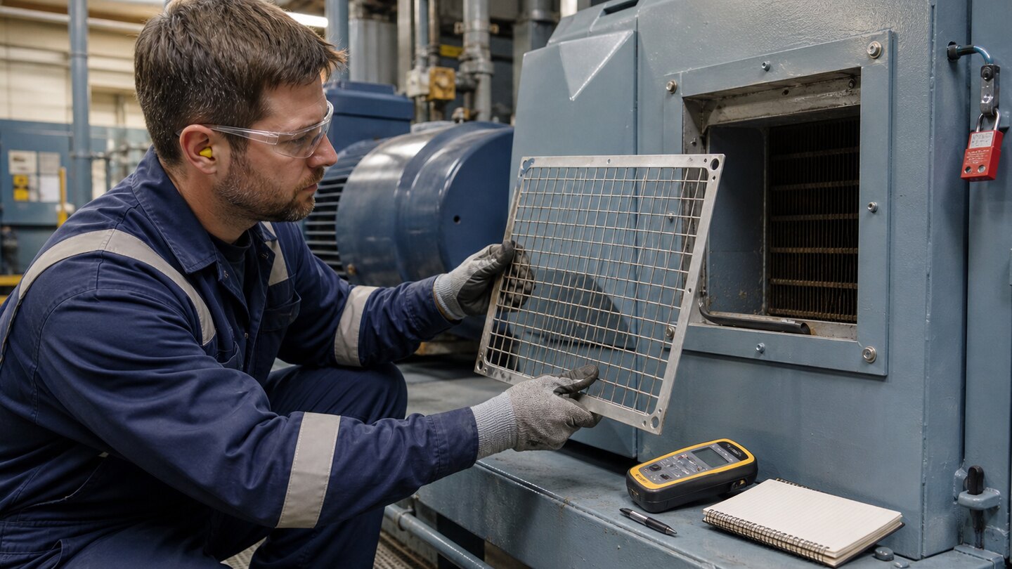
A representative maintenance problem: the replacement guard fits, but the enclosure runs hotter
An industrial maintenance team replaces a damaged ventilation guard on a motor or compressor enclosure. The new panel has the correct outside dimensions, the mounting holes line up and the wire grid appears strong. After restart, however, the enclosure temperature rises and the cooling fan operates closer to its limit. The replacement is not necessarily defective. It may simply present less clear flow area than the original guard.
Suppose the original grid had a 20 × 20 mm clear opening with 2 mm wires. The replacement has a 15 × 15 mm clear opening with 3 mm wires. A visual comparison might focus on the smaller openings or heavier wire. The more useful first calculation is projected open area: the proportion of a repeating mesh cell that is clear rather than occupied by wire.
The Open Area Calculator can compare both square and rectangular grids. It helps an engineer normalize quotations, investigate an unexpected restriction and write a more complete RFQ. It does not predict airflow, pressure drop, acoustic performance or guard strength. Those outcomes require the complete assembly and operating conditions.
What open area means for a wire mesh guard
Open area, sometimes called geometric porosity or percent open area, is a two-dimensional projection. For an orthogonal square or rectangular wire grid, one repeating cell contains a clear opening and the projected width of the wires that bound it. The center-to-center pitch in each direction is therefore the clear opening plus the corresponding wire diameter or projected wire width.
open area (%) = [aₓ ÷ (aₓ + dₓ)] × [aᵧ ÷ (aᵧ + dᵧ)] × 100

aₓ and aᵧ = clear opening dimensions in the two principal directions
dₓ and dᵧ = projected wire dimensions included in those pitches
For a square opening made with equal-diameter wires, the expression simplifies to:
open area (%) = [a ÷ (a + d)]² × 100Use one unit throughout the calculation. Millimetres, inches or micrometres all produce the same percentage if every input uses the same unit. Do not mix a clear opening in millimetres with a wire diameter in inches.
Worked comparison: original guard versus replacement
For the original 20 × 20 mm opening with 2 mm wires, the pitch is 22 mm in both directions. Its calculated projected open area is (20 ÷ 22)² × 100 = 82.64%. For the replacement 15 × 15 mm opening with 3 mm wires, the pitch is 18 mm and the result is (15 ÷ 18)² × 100 = 69.44%.
| Guard construction | Clear opening | Wire | Pitch | Calculated mesh open area |
|---|---|---|---|---|
| Original grid | 20 × 20 mm | 2 × 2 mm | 22 × 22 mm | 82.64% |
| Replacement grid | 15 × 15 mm | 3 × 3 mm | 18 × 18 mm | 69.44% |
The replacement has about 16.0% less projected clear area relative to the original mesh field: (82.64 − 69.44) ÷ 82.64 × 100. That is a meaningful geometric change, even though both panels may be described informally as “open wire guards.”
Panel dimensions add another layer. A 600 × 500 mm panel has a gross face area of 0.3000 m². If mesh covered the entire face, the two mesh constructions would provide theoretical projected clear areas of approximately 0.2479 and 0.2083 m². A real framed panel covers less than the gross face. If a 40 mm solid border leaves a 520 × 420 mm mesh field, the mesh field is only 72.8% of the gross panel face. The original construction then provides about 0.1805 m² of projected clear area, or 60.17% of the gross face; the replacement provides about 0.1517 m², or 50.56%.
This example is an engineering illustration, not a diagnosis of every overheating enclosure. It shows why a replacement should be compared at three levels: mesh-cell open area, usable mesh-field area and total finished-assembly blockage.
Measure the actual construction before calculating
Isolate and lock out the equipment before removing or approaching a guard. Follow the equipment owner's approved procedure; a calculator is never a reason to work near moving or energized machinery. Once the sample is safely available, clean only enough material to expose representative geometry without deforming the grid.
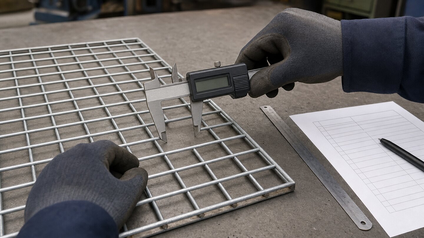
- Identify the construction. Decide whether the sample is welded wire, square-opening woven cloth, pre-crimped screen, perforated plate, expanded metal or a multilayer assembly. The simple rectangular-grid formula does not make these products interchangeable.
- Measure clear opening, not outside-to-outside spacing. Place the caliper jaws across the unobstructed gap between adjacent wires. For a rectangular grid, record both directions.
- Measure wire in the corresponding directions. Round wire normally uses its diameter. Flattened, coated or shaped wire may require an agreed projected dimension and a product-specific method.
- Repeat the readings. Record several representative locations away from cut edges, severe deformation and weld buildup unless those features are the subject of the investigation. Keep individual readings instead of reporting only a convenient average.
- Measure the finished panel. Record gross size, internal frame dimensions, stiffeners, overlaps, fasteners, louvers, filter pads and any downstream obstructions that reduce the usable face.
A photograph can support traceability, but an uncalibrated photograph is not a dimensional inspection system. When tolerance or acceptance matters, state the instrument, resolution, sampling locations and governing inspection method.
Rectangular openings require both directions
Do not calculate a rectangular grid with a square-grid shortcut or an average opening. Consider a welded guard with a 25 mm clear opening and 2 mm wire in one direction, plus a 10 mm clear opening and 3 mm wire in the other. The two directional clear fractions are 25 ÷ 27 and 10 ÷ 13. Multiplying them gives 71.23% open area.
[25 ÷ (25 + 2)] × [10 ÷ (10 + 3)] × 100 = 71.23%The calculator deliberately asks for opening and wire values in both axes. This also makes it useful when comparing an original square grid with a proposed rectangular grid, provided both constructions can be represented as regular orthogonal openings.
Why the same open area does not guarantee the same airflow
Open area is a valuable screening calculation, but airflow is a fluid-system result. Two guards can both calculate to 70% open area and still create different pressure losses. The difference can come from wire shape, thickness in the flow direction, surface roughness, weave crimp, screen layers, approach angle, nearby fan inlet geometry and how rapidly the flow accelerates through each opening.
Operating conditions also matter. Pressure loss changes with velocity and fluid properties. A fan operates on a system curve, so adding restriction can move the operating point rather than merely reducing one isolated number. Dust loading, oil mist, fibres, paint, product buildup and cleaning damage can change resistance during service. Noise and turbulence may become unacceptable before a temperature limit is reached.
Geometry answers
How much of the repeating projected cell is clear? How do two regular grid constructions compare before testing?
Geometry does not answer
What airflow will the installed fan deliver? What pressure drop, noise, temperature or service life will the assembly achieve?
For a critical ventilation duty, define an assembly-level acceptance test: specified airflow at a stated pressure condition, allowable pressure drop at a stated face velocity, maximum stabilized temperature under a representative load, or another measurable requirement chosen by the responsible engineer. Test the finished guard with its frame, backing, filter and mounting arrangement—not only a loose mesh coupon.
Open area is not a guard-safety decision
A high-open-area grid is not automatically an acceptable machine guard. Guard selection must also address access to hazards, opening size and distance from the hazard, impact and deflection, material strength, corrosion, fastening, removal controls and foreseeable misuse. A thinner wire may increase calculated open area while reducing stiffness or damage resistance. A smaller opening may improve one access-control objective while increasing flow restriction.
The applicable machinery safety requirements depend on the machine, location and jurisdiction. Use the machine builder's documentation, the site's risk assessment and the current standards specified for the project. Do not replace an engineered guard on the strength of an open-area result alone.
Which products fit this calculator?
| Product | Use the rectangular-grid formula? | Important qualification |
|---|---|---|
| Regular welded square or rectangular wire grid | Usually suitable for projected geometry | Account separately for frames, weld buildup, coatings and supports. |
| Square-opening woven wire cloth | Suitable for nominal projected geometry | Use nominal aperture and wire diameter; weave and crimp still affect flow. |
| Pre-crimped square or rectangular screen | Can be a first geometric estimate | Confirm how shaped wire and crimp are measured. |
| Perforated plate | No | Use the hole pattern, hole shape, pitch and plate-specific formula. |
| Expanded metal | No | Strand width, bond, SWD/LWD geometry and three-dimensional form require another method. |
| Dutch weave or multilayer filter media | No | Nominal filtration and flow behavior cannot be reduced to a simple visible rectangular opening. |
How standards should appear in the specification
For industrial square-aperture woven wire cloth, ISO 9044:2016 defines terms, requirements and test methods within its stated scope. Its official summary also makes the boundary clear: it does not apply to wire cloth coated after weaving, pre-crimped or welded wire screens. A welded ventilation guard therefore should not be accepted merely by citing ISO 9044.
ISO 4783-2:1989 covers preferred aperture and wire-diameter combinations for woven wire cloth within its scope. Its designation sequence—aperture width, wire diameter, material and weave—illustrates why a purchasing description should contain more than a traditional mesh-count label.
Standards references must match the actual construction and contract. Confirm the current edition, obtain the full document and identify the clauses used for tolerances and inspection. For welded machine guards, use the relevant project drawings, machinery requirements and agreed welded-wire specification instead of borrowing woven-cloth terminology without qualification.
A practical RFQ checklist for ventilation mesh and guards
- Application: intake, exhaust, fan guard, enclosure vent, debris exclusion or another stated duty.
- Construction: welded grid, woven cloth or pre-crimped screen; include weave or crimp style where applicable.
- Geometry: nominal clear opening in both directions, nominal wire dimensions in both directions and calculated open area with the formula basis stated.
- Material and finish: alloy or material grade, coating, surface condition and corrosion environment. Use the Material Selector to organize the exposure questions, not to replace compatibility approval.
- Finished assembly: outside size, usable mesh field, frame, edge treatment, supports, mounting holes, fasteners and permitted protrusions.
- Mechanical duty: required stiffness, impact or load criteria, allowable deflection and support spacing where the responsible engineer has defined them.
- Ventilation acceptance: required flow or allowable pressure loss at stated conditions when performance is critical.
- Inspection: dimensional tolerances, sampling plan, documentation, material certificates, finish acceptance and packaging.
- Commercial data: quantity, unit dimensions and mass estimate. The Wire Mesh Weight Calculator can check nominal net mesh mass, while the supplier must state actual net and packed gross weights.
A five-step tool workflow
- Measure or obtain the clear opening and wire dimensions in both directions.
- Run the values through the Open Area Calculator and save the inputs with the result.
- Calculate the usable mesh-field area after subtracting the frame and solid obstructions.
- Review material, mechanical guarding and installed airflow requirements as separate decisions.
- Compare supplier proposals on the same basis and request an assembly test when geometric comparison is not enough.
If dimensions or duty conditions are incomplete, submit the old panel measurements, photographs, drawing, operating environment and observed problem through Request a Recommendation. The result should become a clearer specification for supplier confirmation, not an unsupported promise of performance.
Frequently asked questions
How do I calculate open area for square wire mesh?
Divide the clear opening by the sum of clear opening and wire diameter, square that fraction and multiply by 100. A 20 mm opening with 2 mm wire gives (20 ÷ 22)² × 100 = 82.64%.
Is 70% open area enough for ventilation?
The percentage alone cannot answer that question. It must be combined with the usable panel area, required flow, face velocity, allowable pressure loss, fan/system behavior, fouling allowance and the rest of the assembly.
Does thinner wire always improve the guard?
Thinner wire increases calculated open area when the clear opening is held constant, but it can change stiffness, impact resistance, durability and manufacturing feasibility. Airflow and guarding requirements must be balanced by the responsible engineer.
Can I calculate the open area from mesh count?
For regular square-opening woven cloth, mesh count plus nominal wire diameter can be converted to nominal aperture and open area. Mesh count alone is insufficient because the wire occupies part of each pitch.
Why does the measured panel differ from the calculator?
The calculator models a regular repeating grid. Measurement tolerance, wire deformation, coatings, weld buildup, crimp, damaged cells and non-mesh obstructions can create differences. Confirm inputs and inspect representative locations.
Does the calculator certify airflow or safety compliance?
No. It calculates projected geometry from user inputs. It does not certify delivered dimensions, material, guard strength, hazard access, pressure drop, fan performance, temperature or regulatory compliance.